Armored Thermocouple
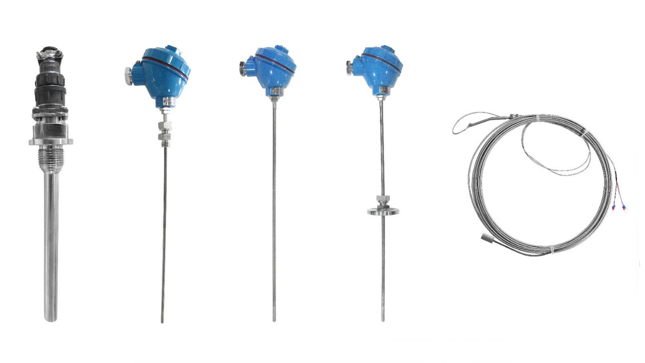
Product Application
The equipment is typically used in conjunction with display instruments, recording instruments, electronic computers, and similar devices. It is designed for the direct measurement of liquid, steam, and gas media, as well as solid surface temperatures in various production processes, with a measurement range of 0~1300°C.
Product Principle
The electrodes of the Armored Thermocouple consist of two different conductor materials. When a temperature difference exists between the measuring end and the reference end, a thermoelectric potential is generated, and the connected instrument then displays the temperature value corresponding to this potential.
Product Features
- Short thermal response time, reducing dynamic errors.
- Flexible mounting/installation.
- Wide measuring range.
- High mechanical strength and excellent pressure resistance.
- Junction box protection rating: IP65, IP66.
Technical Parameters
1. Executive Standard of the Product
- International standard IEC60584.
- National standard GB/T18404, GB/T304292.
2. Room Temperature Insulation Resistance
The insulation resistance of the Armored Thermocouple between the electrode and the outer casing must be ≥ 1000 MΩ when measured at an ambient temperature of (20 ± 15)°C, a relative humidity of not more than 80%, and a test voltage of (500 ± 50)V DC. This minimum resistance applies to a 1m-long specimen (1000 MΩ). For a 10m-long specimen, the minimum insulation resistance is 100 MΩ.
3. Temperature measurement range and tolerance
| Model | Graduation | Tolerance level | |||
|---|---|---|---|---|---|
| I | II | ||||
| Tolerance value | Temperature range | Tolerance value | Temperature measurement range | ||
| WRNK | K | -40 ~ +375 | ±1.5°C | -40 ~ +333 | ±2.5°C |
| 375 ~ 1000 | ±0.004|t| | 333 ~ 1200 | ±0.0075|t| | ||
| WRMK | N | -40 ~ +375 | ±1.5°C | -40 ~ +333 | ±2.5°C |
| 375 ~ 1000 | ±0.004|t| | 333 ~ 1200 | ±0.0075|t| | ||
| WREK | E | -40 ~ +375 | ±1.5°C | -40 ~ +333 | ±2.5°C |
| 375 ~ 800 | ±0.004|t| | 333 ~ 900 | ±0.0075|t| | ||
| WRFK | J | -40 ~ +375 | ±1.5°C | -40 ~ +333 | ±2.5°C |
| 375 ~ 750 | ±0.004|t| | 333 ~ 750 | ±0.0075|t| | ||
| WRCK | T | -40 ~ +125 | ±0.5°C | -40 ~ +133 | ±1.0°C |
| 125 ~ 350 | ±0.004|t| | 133 ~ 350 | ±0.0075|t| | ||
| WRPK | S | 0 ~ +1100 | ±1.0°C | 0 ~ 600 | ±1.5°C |
| 1100 ~ 1600 | ±[1+0.003(t-1100)] | 600 ~ 1600 | ±0.0025|t| | ||
| WRQK | R | 0 ~ +1100 | ±1.0°C | 0 ~ 600 | ±1.5°C |
| 1100 ~ 1600 | ±[1+0.003(t-1100)] | 600 ~ 1600 | ±0.0025|t| | ||
| WRRK | B | / | / | 600 ~ 1700 | ±0.0025|t| |
4. Sleeve Material, Outer Diameter, and Maximum Service Temperature
| Graduation | Sleeve Material | Diameter | Recommended maximum service temperature |
|---|---|---|---|
| K | 0Cr18Ni9Ti | 0.25 | 250 |
| 0.5、1.0 | 400 | ||
| 1.5、2.0 | 600 | ||
| 3.0、4.0、4.5、5.0、6.0、8.0 | 800 | ||
| GH3030 or Inconel600 | 0.25 | 300 | |
| 0.5、1.0 | 500 | ||
| 1.5、2.0、3.0 | 800 | ||
| 4.0、4.5、5.0 | 900 | ||
| 6.0、8.0 | 1000 | ||
| N | 0Cr18Ni9Ti | 0.25 | 250 |
| 0.5、1.0 | 400 | ||
| 1.5、2.0 | 600 | ||
| 3.0、4.0、4.5、5.0、6.0、8.0 | 800 | ||
| GH3030 or Inconel600 | 0.25 | 300 | |
| 0.5、1.0 | 500 | ||
| 1.5、2.0、3.0 | 800 | ||
| 4.0、4.5、5.0 | 900 | ||
| 6.0、8.0 | 1000 | ||
| E | 0Cr18Ni9Ti | 0.5、1.0 | 400 |
| 1.5、2.0 | 500 | ||
| 3.0、4.0、4.5 | 600 | ||
| 5.0、6.0、8.0 | 700 | ||
| J | 0Cr18Ni9Ti | 0.5、1.0 | 300 |
| 1.5、2.0 | 400 | ||
| 3.0、4.0、4.5 | 500 | ||
| 5.0、6.0、8.0 | 600 | ||
| T | 0Cr18Ni9Ti | 0.5、1.0 | 200 |
| 1.5、2.0、3.0、4.0、4.5 | 250 | ||
| 5.0、6.0、8.0 | 300 | ||
| S | GH3039 | 2.0、3.0、4.0、4.5 | 1000 |
| 5.0、6.0、8.0 | 1100 | ||
| R | GH3039 | 2.0、3.0、4.0、4.5 | 1000 |
| 5.0、6.0、8.0 | 1100 | ||
| B | GH3039 | 2.0、3.0、4.0、4.5、5.0、6.0、8.0 | 1200 |
5. Thermal Response Time (t0.5)
| Measurement end form | Armored thermocouple diameter (mm) | |||||||||
|---|---|---|---|---|---|---|---|---|---|---|
| 0.5 | 1.0 | 1.5 | 2.0 | 3.0 | 4.0 | 4.5 | 5.0 | 6.0 | 8.0 | |
| Exposed end type | - | 0.1 | 0.2 | 0.3 | 0.4 | 0.5 | 0.6 | 0.7 | 0.8 | 1.0 |
| Shell type | 0.2 | 0.2 | 0.3 | 0.4 | 0.6 | 0.8 | 1.0 | 1.2 | 2.0 | 4.0 |
| Insulation type | 0.4 | 0.6 | 0.8 | 1.0 | 2.0 | 2.5 | 3.0 | 4.0 | 6.0 | 8.0 |
Measurement end form
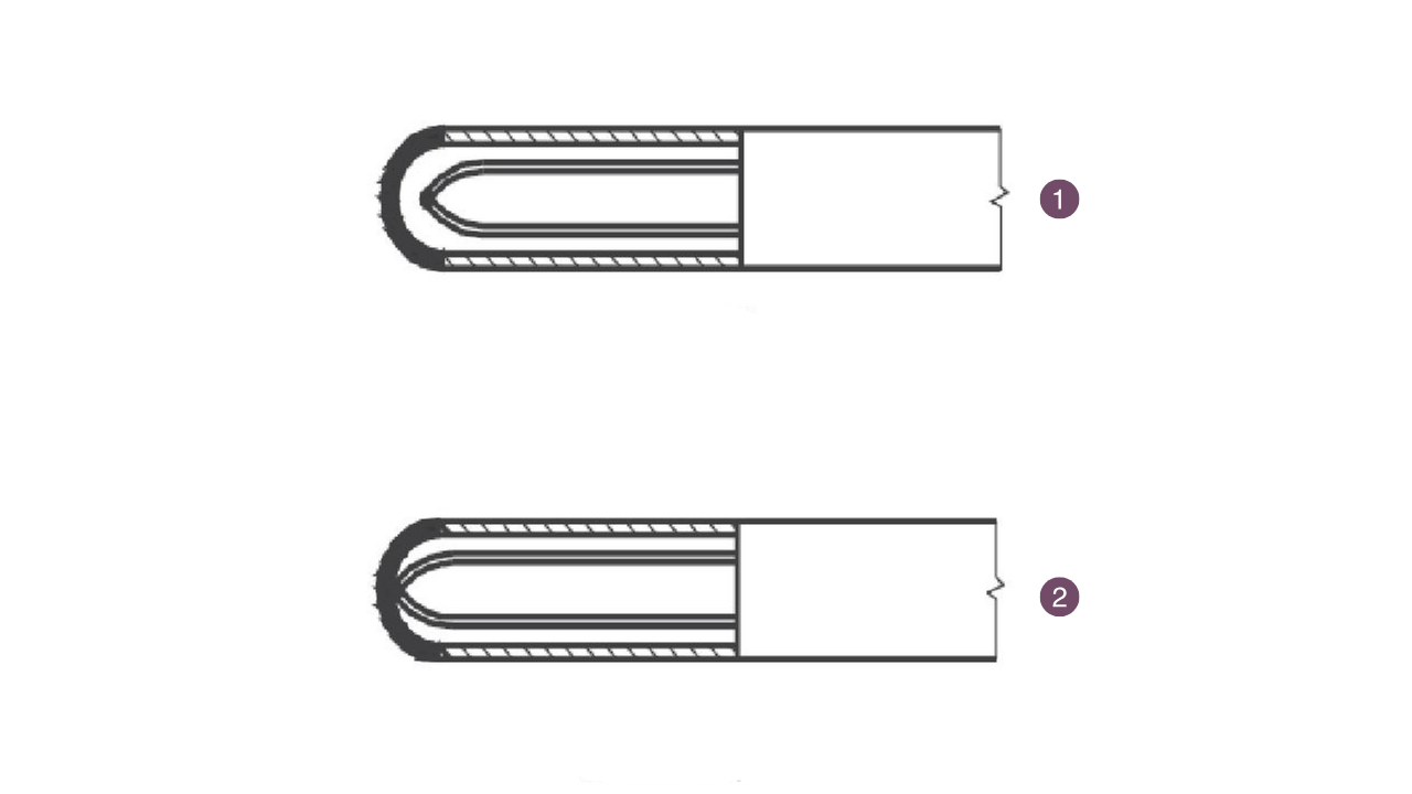
- Shell type
- Insulation type
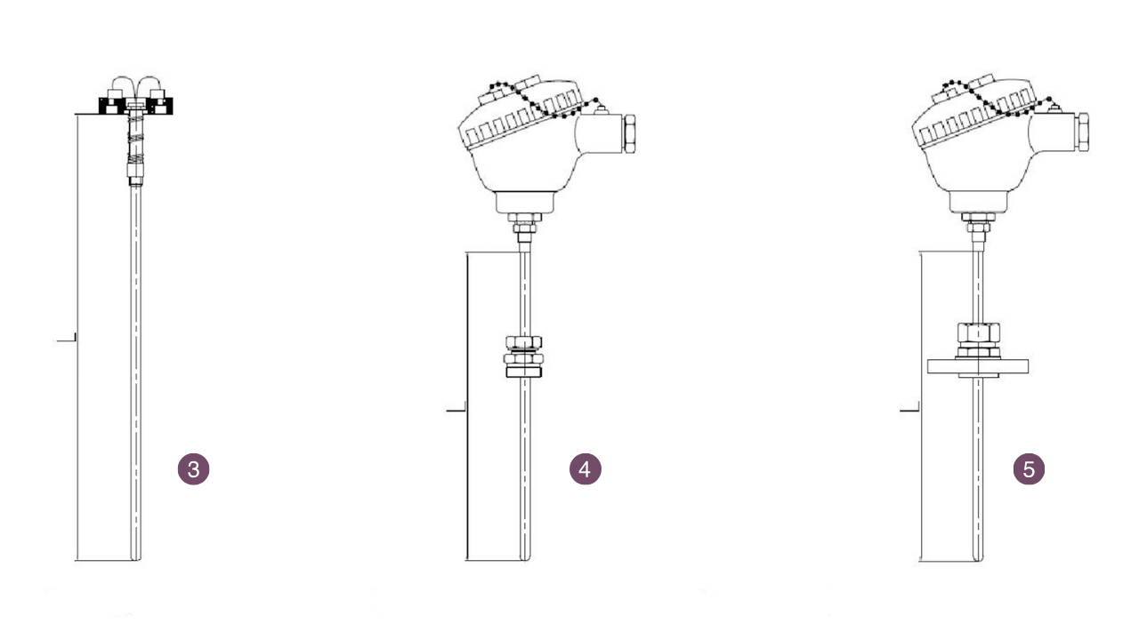
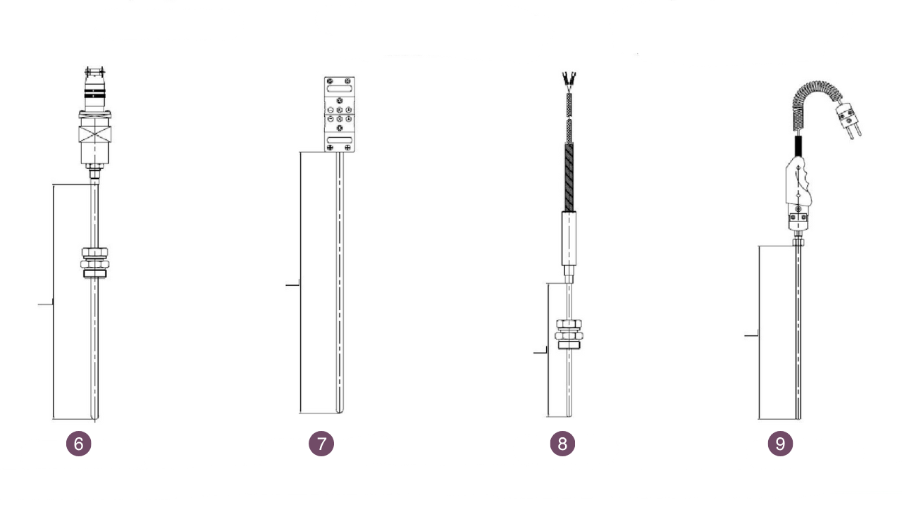
Terminal box form
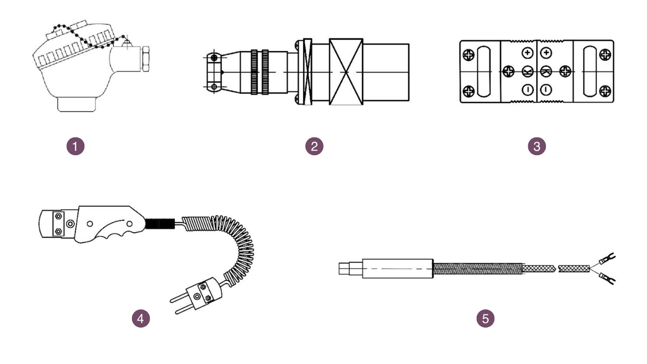
- Waterproof
- Round plug-in type
- Plug-in type
- Handle type
- Compensating conductor type
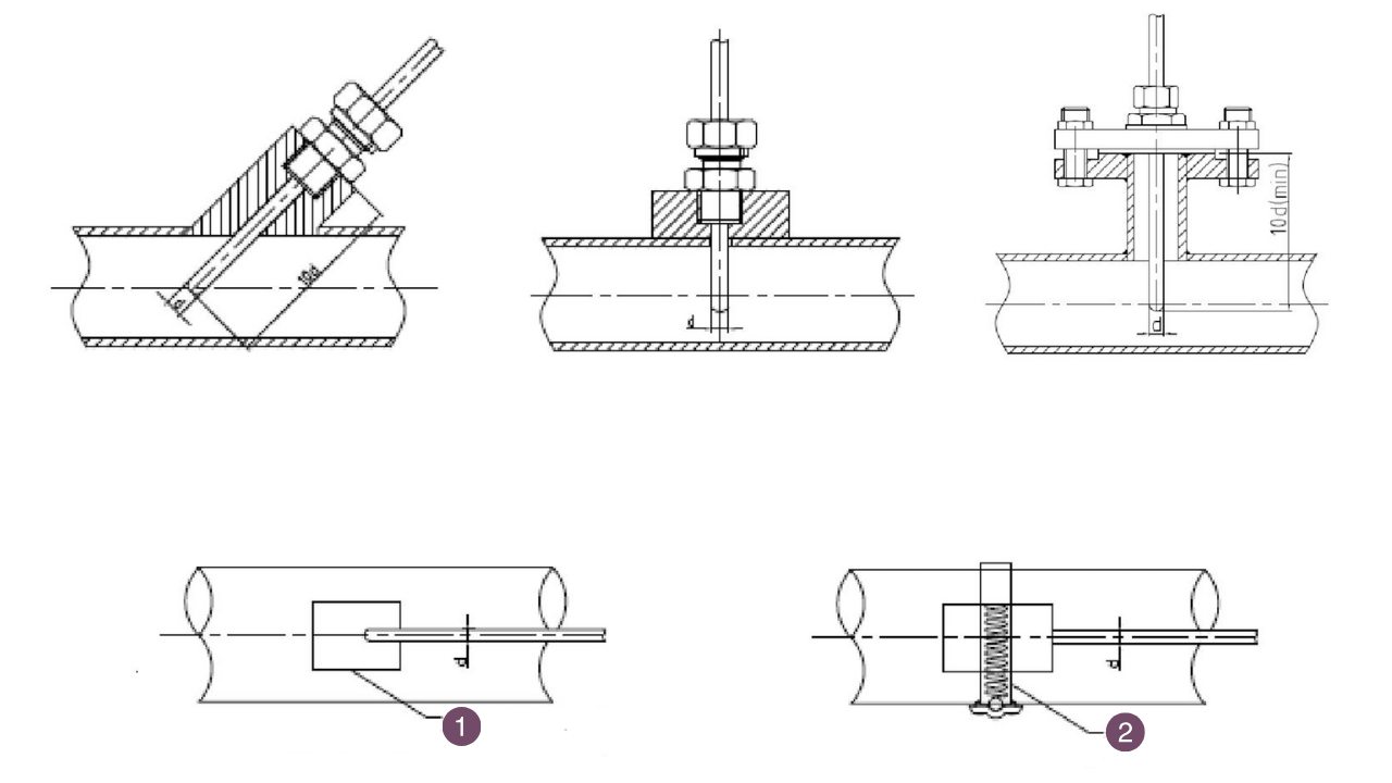
6. Installation of fixed devices
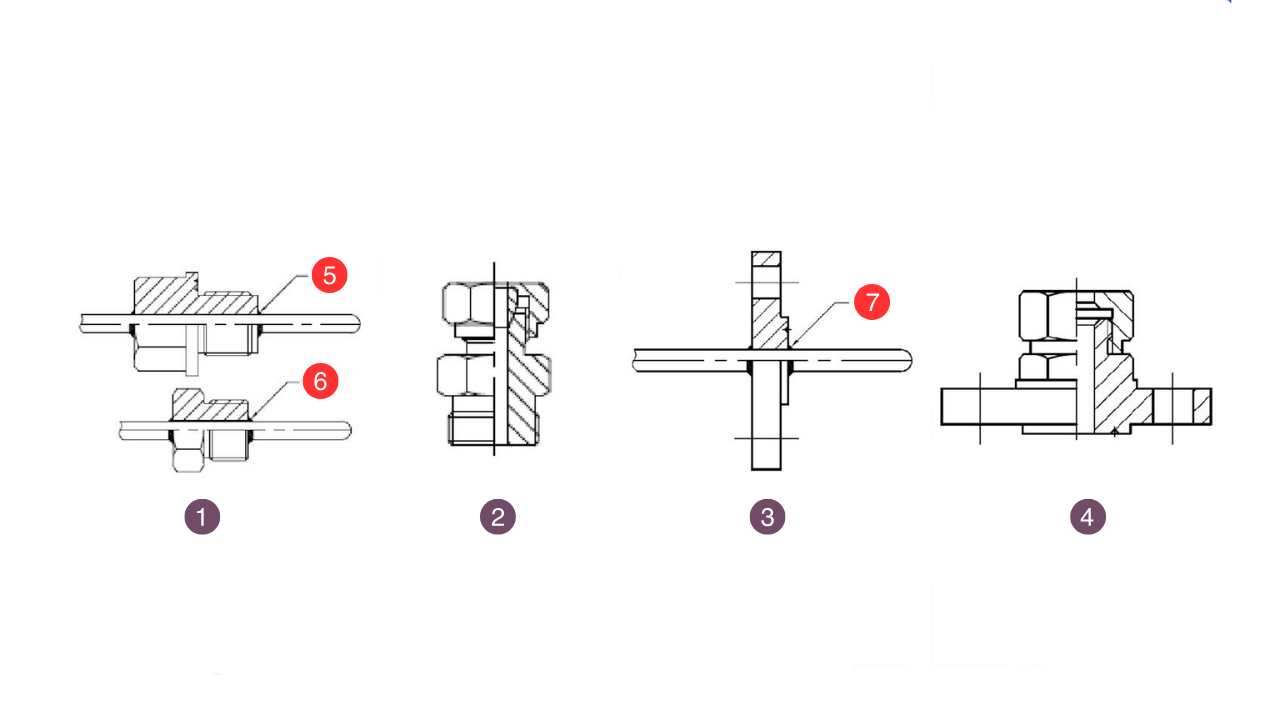
- Fixed thread
- Adjustable ferrule thread
- Fixed flange
- Adjustable ferrule flange
- Welding
- Welding
- Welding
7. Additional installation form
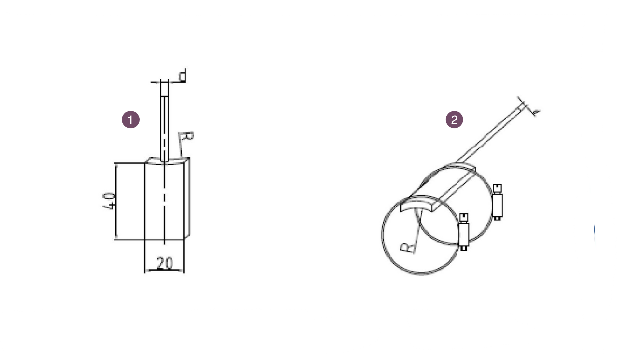
- Contact block type (code M).
- Hoop type (code G)
Model Naming Method
Structure diagram
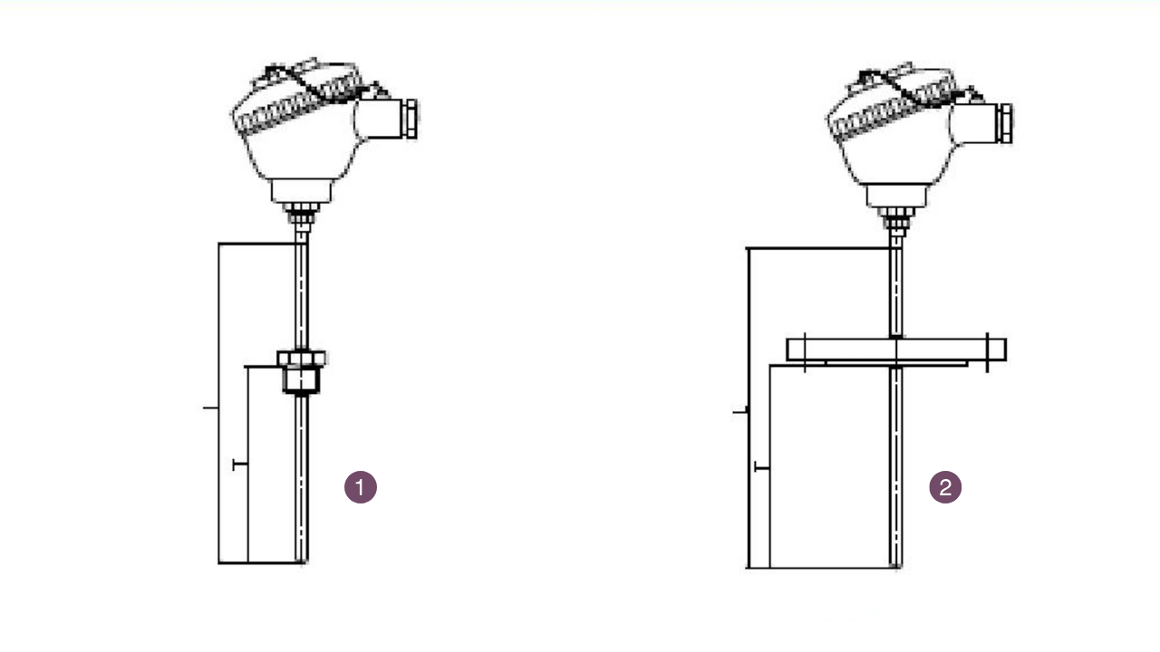
- WRNK-235 (Fixed thread)
- WRNK-435 (Fixed flange)
- WRNK-010
- WRNK-335 (Adjustable ferrule thread)
- WRNK-535 (Adjustable ferrule flange)
- WRNK-365
- WRNK-275
- WRNK-295
- WRNK-185
Installation form
- Welding of contact block to pipe
- Hoop fixing
Selection Instructions
- Model.
- Graduation number.
- Accuracy level.
- Installation and fixation form.
- Protective tube material.
- Length or insertion depth.
Contact Us
SiO2 Non-zero Dispersion Single Mode Optic Fiber - G.655/B4 Fiber
Non-zero dispersion-shifted (NZDS) single-mode optical fiber for long-haul DWDM systems and low-dispersion telecom applications.
Assembly Thermocouple
Pre-assembled thermocouple assemblies with sheath and connector options for fast installation and reliable field performance.