The K-Type Thermocouple
For any technician wrestling with industrial temperature control, the K-type thermocouple isn't just another sensor; it’s often the backbone of their process. From sprawling chemical plants to precision manufacturing lines, this ubiquitous sensor is the unsung hero, constantly feeding critical temperature data. But here’s the rub: its very ubiquity can breed a dangerous familiarity. We trust it implicitly, often overlooking the subtle nuances and common pitfalls that can turn a reliable reading into a catastrophic error. This isn't a fluffy overview; this is a deep dive into mastering the K-type, understanding its quirks, and sidestepping the headaches it invariably throws your way.
Why K-Types Dominate: The Unbeatable Combination of Range and Robustness
The K-type earned its stripes through sheer versatility and ruggedness. It leverages Chromel (a nickel-chromium alloy) and Alumel (a nickel-aluminum alloy), giving it a phenomenal operating range: typically from -200°C to 1250°C. Think about that span for a moment – from cryogenic applications to the roaring heart of a steel furnace. No other single thermocouple type matches this breadth while remaining relatively cost-effective and mechanically durable.
Technicians gravitate towards the K-type for several reasons:
- Wide Temperature Span: As mentioned, its range makes it suitable for countless industrial processes without needing specialized, expensive alternatives.
- Cost-Effectiveness: Compared to platinum-rhodium thermocouples (like Type R or S), K-types are significantly cheaper, making large-scale deployments feasible.
- Robustness: With proper sheathing, K-types withstand harsh industrial environments, resisting vibration and corrosion surprisingly well.
- Standardization: Its widespread use means readily available controllers, indicators, and extension wires, simplifying integration.
But this dominance isn't without compromise. While robust, K-types suffer from higher drift rates at elevated temperatures compared to noble metal thermocouples and can be susceptible to green rot in specific reducing atmospheres. In these conditions, the chromium preferentially oxidizes, altering the alloy composition and causing a significant drop in voltage output (drift), rather than just mechanical failure. Understanding these limitations is just as critical as knowing its strengths.
The Seebeck Effect: More Than Just mV, It's About Potential Difference
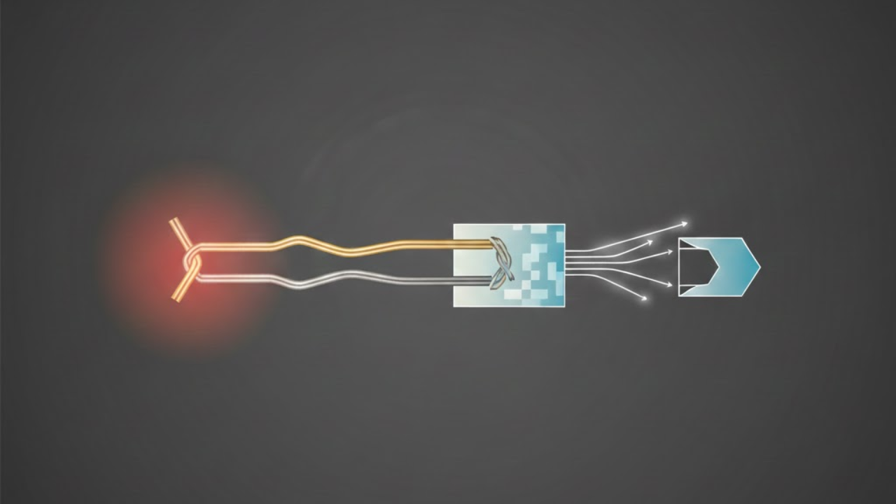
At its core, the K-type, like all thermocouples, operates on the Seebeck effect. When you join two dissimilar metals and subject one junction to a temperature difference relative to the other, a voltage develops. This thermoelectric voltage (or electromotive force, EMF) is directly proportional to the temperature difference. For a K-type, that EMF is roughly 41 microvolts per degree Celsius (µV/°C) at room temperature – not a huge signal, which immediately tells you why noise can be such a problem.
This brings us to the linchpin of accurate thermocouple measurement: Cold Junction Compensation (CJC). The sensor itself measures the difference in temperature between its hot junction (where you want to measure) and its cold junction (where the thermocouple wires connect to your measuring device). Without knowing the temperature of that cold junction, your reading is essentially meaningless. It's like trying to measure a distance with a ruler, but you don't know where the ruler's zero point is.
Modern instruments handle CJC internally, typically with a thermistor or RTD sensing the ambient temperature at the input terminals (the "Isothermal Block"). Technicians must grasp two critical CJC issues:
- Stable Environment: If the ambient temperature around the cold junction fluctuates wildly, the internal CJC sensor might lag, introducing transient errors.
- External CJC (Older Systems): If you're dealing with older systems or junction boxes, external CJC might be used. Ensure the compensating lead wires or reference junction is truly at the reference temperature your instrument expects.
Anatomy of a Reliable Installation: Beyond Plugging it In
Getting accurate, repeatable readings from a K-type demands more than just sticking it in the process. It involves meticulous attention to the physical installation.
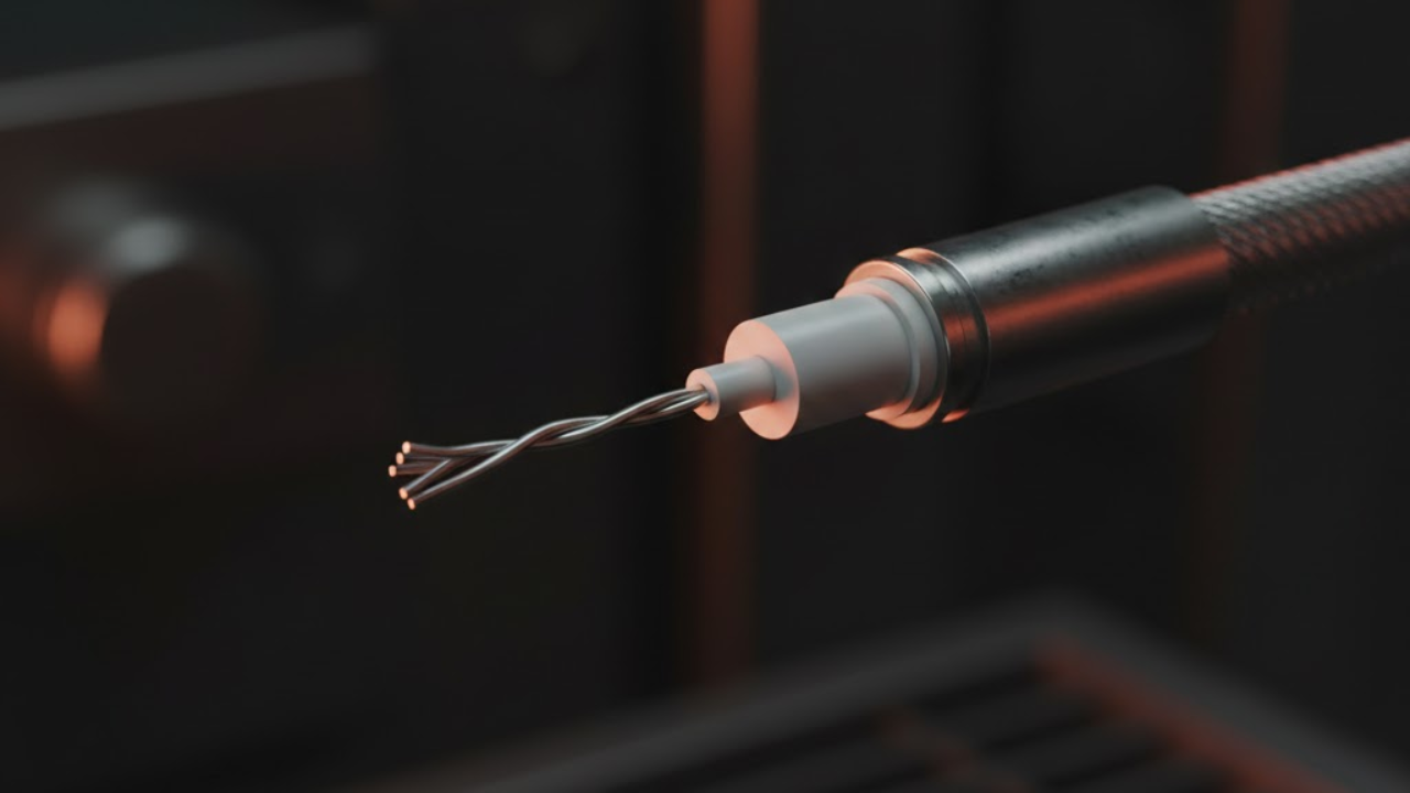
Sheathing & Insulation: Your First Line of Defense
The bare Chromel-Alumel wires are fragile. Industrial K-types almost universally come sheathed, typically as Mineral Insulated (MI) cable. This construction involves the thermocouple wires embedded in highly compacted magnesium oxide (MgO) powder, all encased in a metal sheath (e.g., Inconel 600, SS316, SS304). This isn't just for protection; MgO provides excellent electrical insulation and helps maintain wire integrity at high temperatures.
- Inconel 600: Superb for high-temperature and corrosive applications.
- SS316: Good all-rounder, offers decent corrosion resistance.
- SS304: More economical, but less resistant to certain corrosives and high temps.
Match the sheath material to your process environment. Using a SS304 sheath in a highly corrosive environment is asking for premature failure and costly downtime.
Immersion Depth: The "10x Diameter" Rule Isn't Optional
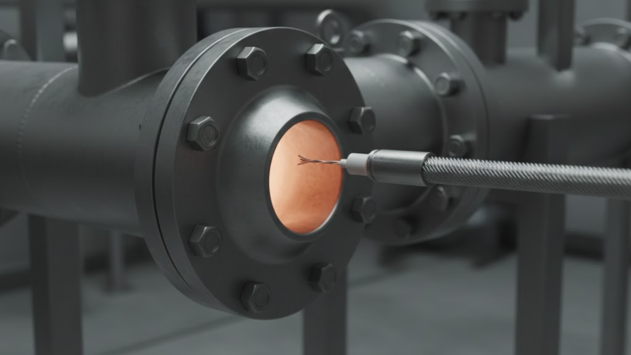
One of the most common, yet overlooked, sources of error is insufficient immersion depth. The sheath itself acts as a heat sink, drawing heat away from the hot junction. If the thermocouple isn't immersed deep enough into the process, the hot junction will measure a temperature lower than the actual process temperature. A good rule of thumb is to immerse the tip at least 10 times the outside diameter of the sheath into the medium you're measuring. For a ¼-inch sheath, that means 2.5 inches of immersion. Anything less, and you're essentially measuring an average of the process temperature and the ambient temperature around the sheath.
Wiring it Right: The Path from Sensor to Controller
This is where many technicians stumble. You absolutely cannot use standard copper wire to extend a thermocouple circuit. Doing so introduces another thermocouple junction (copper-Chromel, copper-Alumel) with its own thermoelectric properties, creating an unwanted and inaccurate voltage. You must use dedicated thermocouple extension wire (Type KX for K-types) that matches the original thermocouple's metallurgy.
Pay close attention to Color Codes:
- ANSI (USA): Yellow (+) and Red (-).
- IEC (International/Europe): Green (+) and White (-). Check your specific regional standard to avoid reversing polarity.
- Polarity Matters: Reversing polarity generates a negative voltage relative to the temperature rise, leading to wildly incorrect readings (or protection trips).
- Shielding & Grounding: Thermocouples generate tiny millivolt signals, making them highly susceptible to electrical noise (EMI/RFI) from motors, VFDs, and power lines. Use shielded extension cables and ground the shield at one end only (typically at the instrument) to prevent ground loops. Run thermocouple wires away from power cables where possible.
The K-Type's Achilles' Heel: Common Failure Modes & Troubleshooting

Even with meticulous installation, K-types eventually fail. Knowing how they fail is key to rapid diagnosis.
Open Circuits: The "No Reading" Nightmare
An open circuit means the electrical path is broken. Your controller will typically show an open circuit error, or drive the reading to the full-scale limit (Upscale or Downscale Burnout) to ensure safety. In simple devices, it might display 0 (which can be dangerous if 0°C is a valid process value). Causes include:
- Physical Damage: Kinks, cuts, or excessive bending of the sheath or wires.
- Internal Wire Break: Often due to thermal cycling fatigue or excessive vibration, especially near the hot junction.
- Corrosion: Aggressive chemicals eating through the wires or sheath.
Diagnosis: Disconnect the thermocouple from the instrument. Use a multimeter on the resistance (Ohms) range. You should get a low, stable resistance reading (typically 2-50 Ohms depending on length and gauge). An OL (open loop) or infinitely high resistance indicates an open circuit.
Short Circuits/Ground Faults: The "Wrong Reading" Headache
This occurs when the two thermocouple wires short together, or one (or both) wires short to the metal sheath. This effectively moves the hot junction to the point of the short, leading to an incorrect, often lower, reading.
- Causes: Insulation breakdown (MgO becoming conductive due to moisture ingress or damage), physical compression of the sheath, repeated thermal cycling stressing the wires.
Diagnosis: For a short between wires, a multimeter will show a lower-than-expected resistance. For a ground fault, use your multimeter to check resistance between each thermocouple wire and the sheath (if it's an ungrounded junction). Any low resistance reading here indicates a fault.
Decalibration & Drift: The Sneaky Saboteurs
This is the most insidious failure mode because the thermocouple appears to be working, but its readings are consistently off. Decalibration is a permanent change in the thermocouple's thermoelectric characteristics.
- Causes: Prolonged exposure to high temperatures, thermal cycling, contamination from impurities migrating into the alloys, or
green rot(preferential oxidation of Chromel in reducing atmospheres). - Symptoms: Readings slowly creep, consistent offset from known good temperatures, or discrepancies between multiple sensors in the same process.
Diagnosis: Requires comparison against a known, accurate reference (e.g., a calibrated reference thermocouple, a blackbody calibrator, or an ice bath/boiling water test). This is why regular calibration verification is non-negotiable for critical applications.
Cold Junction Compensation Errors: The Software & Hardware Mismatch
While we touched on CJC earlier, its failure directly translates to reading errors.
- Causes: Damaged or miscalibrated internal CJC sensor, rapid ambient temperature changes overwhelming the CJC circuit's response time, improper external CJC placement, or simply using the wrong input type for your instrument (e.g., setting it for RTD when it's a thermocouple).
- Symptoms: A consistent offset in readings that might vary with the ambient temperature around the instrument's terminals.
Diagnosis: Use a precision temperature reference to measure the actual temperature at the instrument's terminals. Compare this to the instrument's reported cold junction temperature (if available). If the instrument thinks the terminal is at 40°C when it is actually at 25°C, your process reading will be offset by approximately that difference (15°C).
Your Toolkit for K-Type Success: Best Practices

Mastering the K-type thermocouple isn't about memorizing specs; it's about understanding its behavior in your system. Implement these practices to keep your process temperatures accurate and your troubleshooting swift:
- Standardize & Document: Use consistent K-type models across similar applications. Document installation depth, sheath material, and connection points.
- Buy Quality: Cheap thermocouples often mean cheap wire and impure insulation, leading to early decalibration or failures. Invest in reputable brands with high-purity MgO.
- Regular Verification: For critical processes, periodically check thermocouple readings against a known reference. Don't wait for a process upset.
- Protect the Wires: Use conduit or cable trays to protect extension wires from physical damage, moisture, and EMI.
- Respect the Polarity: A simple double-check against the correct standard (ANSI vs IEC) at installation can save hours of troubleshooting.
- Understand Your Environment: Is it corrosive? Prone to vibration? High temperatures? Select sheathing and construction accordingly.
The K-type thermocouple remains an indispensable tool for technicians. It's affordable, versatile, and robust – but it's not foolproof. By understanding its fundamental principles, meticulously installing it, and knowing its common failure modes, you can elevate your temperature measurement game from reactive firefighting to proactive process control. Don't just install it; master it.